-40%
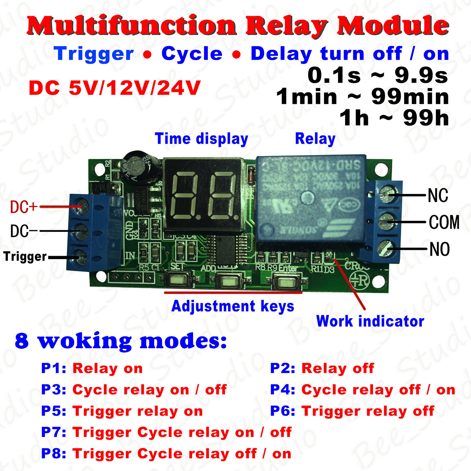
Multi-function Voltage control Relay Timer Delay Switch Voltage Protection 12V
$ 3.61
- Description
- Size Guide
Description
Product OverviewMulti-function Voltage control Relay Timer Delay Switch Voltage Protection 12V
Operating modes:
P-1: Timer ( 1-999 S / 1-999 Min)
P-2: Delay timer ( 1-999 S / 1-999 Min)
P-3: Voltage control relay ( control the load on/off)
P-4: Voltage control Timer- A (release first)
P-5: Voltage control Timer- B (close first)
P-6: Voltage range control relay
P-7: Voltage range control Timer
P-8: Set display off
Timing Range: 0-999 seconds or 0-999 minutes (0.1s-999s optional)
Voltmeter display range: DC 0-99.9 V
Voltage detection error: ± 0.1V
Operating Power: DC10~16V (5V,24V optional)
Relay parameters:
Coil Voltage: DC 12V (5V,24V optional)
A set of conversion (normally open and normally closed)
Contact load: 10A/277V AC or 10A/30V DC
Contact resistance: ≤ 100mΩ (1A 6VDC)
Mechanical durability: 10 millions
Electricity durability: > 100,000 (10A-250VAC)
Operating Temperature: -40 ~ 85℃
External signal input: (5~ 12V) or passive switch (9 levels delay time can be set)
Timer mode can set the relay contact close and release time, the implementation of a single timing loop
In voltage control mode, can preset upper and lower voltage values limits
Set display shut, the minimum current values are 6mA/12V (delay released)
The pre-set parameters can be saved after power off.
2 operating modes:
Connect to power, LED digital tube displays words "E-A-Z-Y-t” in turn, system enter into the selection state, the initial mode selection is displayed as "P-0", press the “SET” button to select "P-1~P-8" mode, press “ENTER” to enter the corresponding mode.while any mode running, press the “ENTER” button for 3 seconds, system will return to the mode selection state.
Press the “SET” and “ENTER” button to connect the power, the controller will be restored to factory settings.
2.1 Timer mode (P-1)
Press the “SET” button to select "P-1", controller system will enter into the timer mode.
“P-1”/ “P-2”: 1-999 seconds /minute can be set.
Cyclic run:
In the timer mode, the user can set the relay’s close time T1 and the release time T2,such as setting T1 for 3 seconds, T2 for 7 seconds, the relay will be closed for three seconds then release for 7 seconds, cyclic run.
User also can set cyclic times.
When you have set the values of the T1 and T2 , the system saved the settings, the next time system will be loaded automatically T1 time to wait running.
Timer:
If you set T1 with a specified time, set T2 (release time) with 0, the relay will stop after the timer run T1 time, no longer running, it can be used as a timer, with running time end, the normally open contact of relay release, then press the “ENTER” button, the system re-start the timer for T1 time.
In timer state, you can use external switch or pulse signal input Interface (Figure 1)on controller to start the timer (trigger).
Timer setting steps:
1)
For the first time of set , select "P-1” time relay mode, LED digital tube display" 000 ";
2) Press the “SET” button, system will enter into the T1 time values settings first, the digital LED that wait for set flashing with 1Hz frequency, press “ENTER” to select the number of values, press the “SET” button for three times to enter the T2 time values settings, and cyclic times, press the “SET” button to exit the set state, the system waits to press “ENTER” button to start running.
3) In the time setting state ,time values’ unit can be switched to minutes unit or second unit, press the “SET” button to enter the time set by state (set LED digital tube flashing) ,at this time Press the “SET” button for 3 seconds to release ,the LED digital tube will light the right decimal points, it means that timing values with minutes unit, if the decimal point dose not light, it means that timing values with seconds unit.
4) After setting is completed, press the “SET” button to exit the setting state, press “ENTER” to start timing, if timing values is set with second unit, seconds values will display with countdown form. If timing values is set with minute unit, the right decimal point flashing with 1Hz frequency, means the countdown is running. While timer is running, the normally open contact of relay connected, the normally closed contact of relay disconnect, press the “ENTER” to halt run, press the “ENTER” for three seconds to return mode selection state “P-0”.
2.2 Delay timer (P-2)
The Setting method of “P- 2” is the same as “P- 1”, in the mode of “P-2”, the relay will first execute release of T1 time then closed with T2 time.
2.3 Voltage control relay mode (P-3)
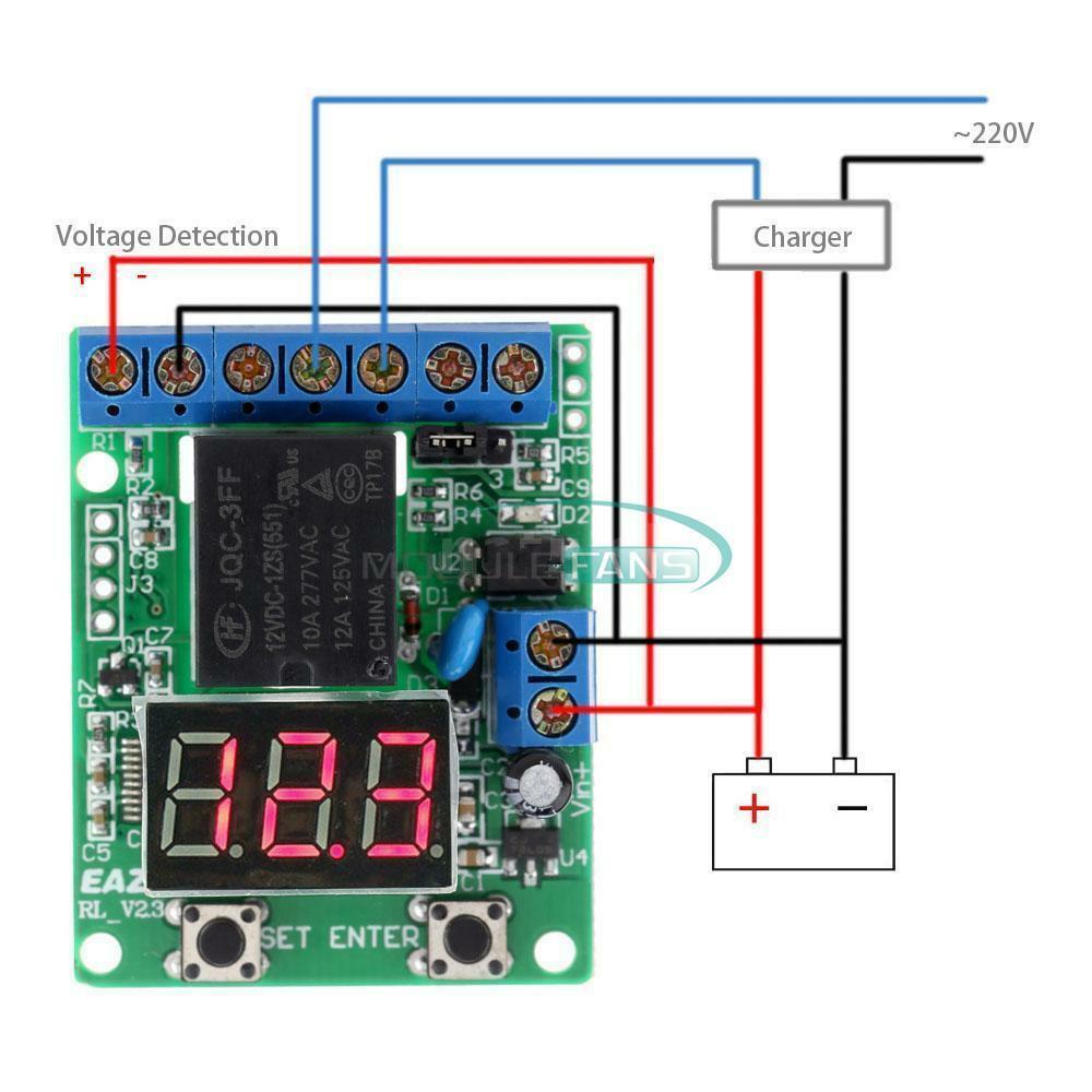
In mode selection state(“P-0”), press the “SET” button to select "P-3", then press the “ENTER” to enter the voltage comparison control mode, the controller will detect voltage from “VOL” Interface ( Figure 1)and display values (DC 0-99.9V),it also can be used as a DC voltmeter ,the default initial run state relay contact is closed (normally closed contact is disconnected, normally open switch on), press the “SET “button to set the three bit values, the LED digital tube is set to flashing with1Hz frequency, first to be set upper limit voltage values , press the “SET” button three times, lower limit values of voltage to be set,press the “ENTER” button to increase the number of values, the lower limit voltage can not exceeds the upper limit, press the “SET” button to make digital tube is no longer flashing, this time system enter into voltage control mode , the controller detects DC voltage from external input Interface ( Figure 1) , when voltage detection exceed the upper limit of the pre-set, the relay close (normally open contact connect ,normally closed disconnect), until the voltage drops below the lower limit pre-set, the relay will release (normally closed contact connect , normally open contact disconnect).
In voltage control condition, press the “SET” button for three seconds then release the button, the contact of relay state will be reversed. such as: the relay close when detect voltage below the lower limit voltage.
If the pre-set voltage upper and lower limits set to the same, such as 12.0V, when controller detect volts at 12.0 fluctuations may cause the relay contact frequent action, we recommend to set the voltage to maintain the difference between the upper and lower limits.
Note: The detection voltage terminal must connected reliable, have not loose wiring around the circuit board insulation ,may lead to the induced voltage detection values is not accurate.
2.4 Voltage control Timer mode (P-4 / P-5)
“P-4” or “P-5” mode is composed of “P-1” and “P-3” or “P-2” and “P-3”.When the system switched to “P-4” from “P-1”or“P-2”,it will enter the voltage control timer mode, the controller will detect voltage from “VOL” Interface ,when detect voltage exceed the upper limit of the pre-set voltage, the timer will start , until the volts drops below the lower limit pre-set , the timer stop.
If you set time in “P-1” mode previous, then enter the “P-4” mode , the relay will close with timer first ,then release, If you set time in “P-2” mode previous, then enter the “P-4” mode ,the relay release with timing then closed.
The difference between “P-4” and “P-5” is the relay’s Initial state, “P-4” mode relay release first, but “P-5” mode relay close first.
Press the button of “SET” last for 3 seconds, the timer will start in the case of the voltage is below the lower limit. the setting method of limit pre-set voltage, please refer to section 2.3.
For example:
(1) In P-2 mode , set T1 005, T2 000, then enter P-4 mode , voltage detection exceed the upper limit of the pre-set the relay will close after 5 seconds, voltage drops below the lower limit pre-set the relay release Immediately.
(2) In P-1 mode , set T1 005, T2 000, then enter P-5 mode, voltage below the lower limit pre-set the relay close immediately, voltage detection exceed the upper limit of the pre-set the relay will release after delay 5 seconds.
Voltage control logic can be reversed with press SET key for 3 seconds.
2.5 Voltage range control relay (P-6)
If the voltage controller detects exceed the upper limit of the pre-set voltage, or the voltage drops below the lower limit pre-set voltage, the relay will close, otherwise the relay release between upper limit and lower limit range. Press the button of “SET” last for 3 seconds, the relay reversed. The relay will close between upper limit and lower limit.
2.6 Voltage range control Timer (P-7)
If the voltage controller detects exceed the upper limit of the pre-set voltage, or the voltage drops below the lower limit pre-set voltage, the relay will run follow time relay mode that has been set in P-1 or P-1 mode previous.
When voltage values between the upper limit and lower limit range, press SET key for 3 seconds, relay reversed between close and release (ON/OFF).
For example:
In P-1 mode, set T1 005, T2 000, then enter P-7 mode, set relay close between upper limit and lower limit range. When voltage below lower limit or exceed upper limit, the relay will release after 5 seconds.
2.7 Set display shut (P-8)
The display shows “d-0” means keep bright, you can press the button of “SET” set 0-9 minutes for display shut.
Package Included:
1 x Relay Switch Control Module
Shipping Policy
Item Location
Payment Mathord
Returns Policy
About Feedback
Shipping Policy
1. We Ship to Worldwide
2. We ship your orders within 1-2 business days after the payment cleared.
3. Item shipped from China via china Post Airmail, reach most of the countries within 2 to 4 weeks.
4. Delivery time depends on destination and other factors, it may takes up to 20 days. If you don't receive
the item after 25 days,please keep in touch with us, we'll investigate and solve the delivery problem.
5. Import duties, taxes, and charges are not included in the item price or shipping cost. These charges
are the buyer's responsibility. Please check with your country's customs office to determine what these
additional costs will be prior to bidding or buying.
Item Location
ShenZhen
Payment Mathord
1. We accept PAYPAL only.
2. Payment must be made within 7 days of auction closing (Unpaid dispute will automatically open when item
is not paid in 7 days).
3. PLEASE NOTE: SHIPPING&HANDING DOES NOT INCLUDE DUTIES, LOCATL TAXES OR ANY OTHER IMPORTATION FEES.
4. Please list your special requests (color, packages, value of declaration, etc.) in the EBAY NOTES SECTION
when you make payment
Returns Policy
1. Customer satisfaction is our top goal. All products are quality checked. They are new and in good
condition when shipped to our customers. If product is defective or damage upon arrival, or wrong
product shipped, please keep in touch with us immediately. Returns accepted within 14 days of delivery date
and item must be in original new condition, not worn or altered in any way with attached tags & wrap.
Otherwise deal is final. Return shipping must be paid by buyer.
2. Please keep in touch with us first if you have anyproblems/questions/concerns. We will be happy to resolve
any issues you may have in a cordial and friendly manner.
3. We appreciate your Positive Feedback, and will do the same in return. PLEASE DO NOT leave
negative feedback without first communication with us. Please allow max 24 HOURS for us to respond
About Feedback
We maintain high standards of excellence and strive for 100% customer satisfaction! Feedback is
very important to us. We request that you keep in touch with us immediately BEFORE you give us neutral or
negative feedback, so that we can satisfactorily address your concerns.It is impossible to address
issues if we do not know about them!
